
Inside Opus · Part 12 of 13
This series follows a hypothetical supplier-invoice exception workflow. The previous articles described the services that run it. This article is about the infrastructure they run on. Part 1, “A piece of work through Opus”, is the map.
Same workflow, two clouds
Two customers want the same invoice exception workflow. One runs on AWS, with a network team that insists on private subnets and a security team that wants to know exactly which endpoints are reachable from the internet. The other runs on Azure, has an existing Kubernetes practice, and wants to operate the environment itself.
The workflow does not care. The executor, the agent loop, the authorization model and the marketplace are the same in both. The infrastructure underneath them is not, and pretending otherwise is how deployments go wrong.
The requirement
The deployment must provide a fixed set of logical responsibilities on either cloud, must draw its boundaries so that what is reachable from where is explicit, must separate workloads with different resource needs, and must be honest about which parts are shared, which are per-tenant and what each choice costs to operate.
The logical responsibilities
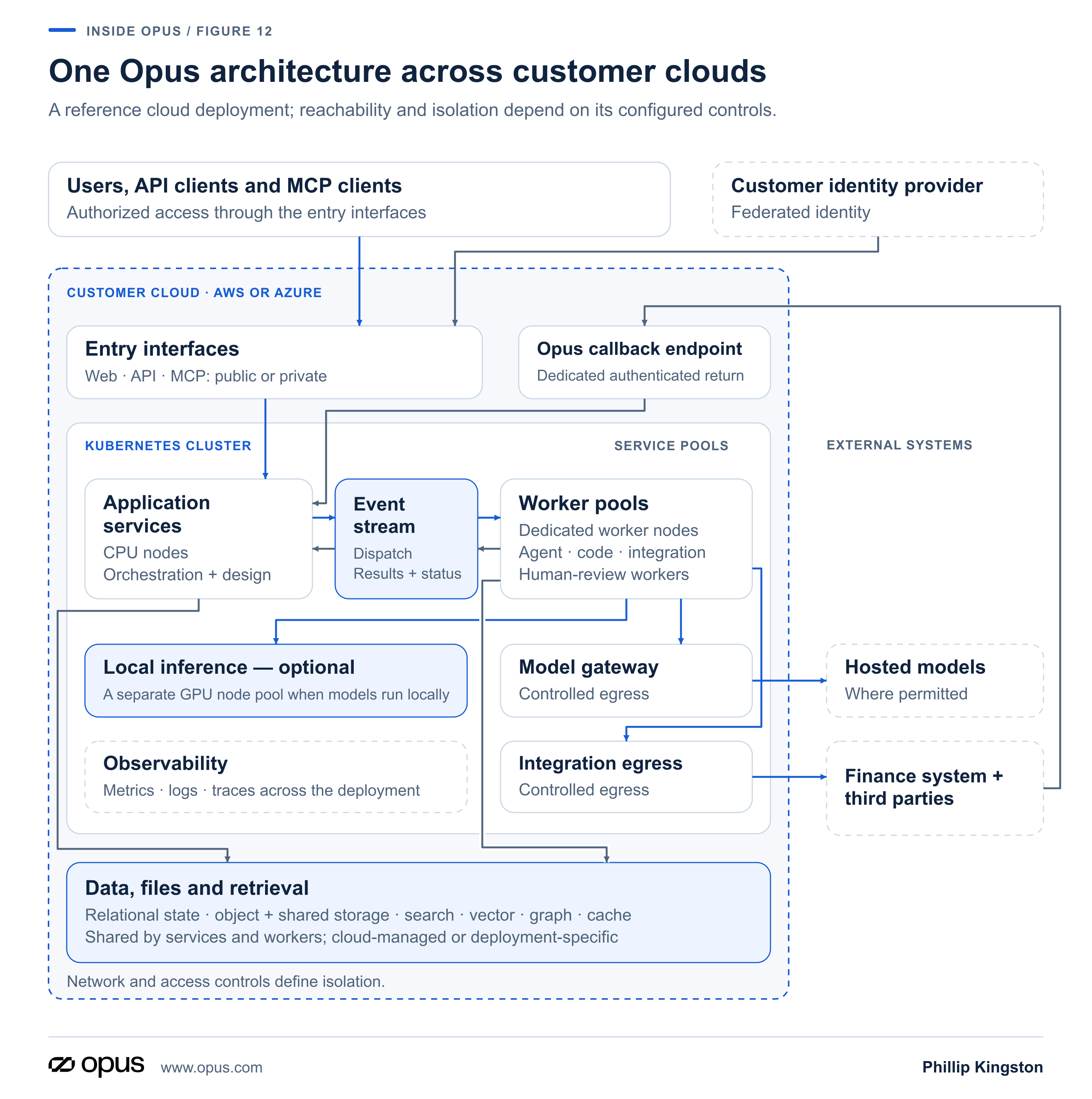
Start with roles, not products. In the reference cloud deployment described here, Opus application services run inside Kubernetes, supported by in-cluster components and cloud-managed services. The arrangement provides these responsibilities:
Entry interfaces. The web application, the API server and the MCP server, each behind its own hostname.
Identity. Federation with the customer’s identity provider, and the identity, billing and usage service that attributes actions and meters use.
Execution services. The central orchestrator, the collaboration service, the workflow and agent trace services, and the design-time services described in Part 4, Part 5 and Part 6.
Worker pools. Agent, code, integration and review workers, as separate groups.
Event transport. A distributed event stream carrying dispatch, results and status.
Persistent state. A relational database for platform state.
Files. Object storage for uploads, generated files and workflow outputs, plus shared file storage where services need a filesystem.
Retrieval. A search index, a vector store and a graph data store, together with a cache.
Inference. A private model gateway to hosted models, and in-cluster model serving where the private-inference options from Part 8 require it.
Observability. Metrics, logs and traces.
Everything in a concrete deployment is an implementation of one of those roles.
The boundaries
Each deployment must specify which interfaces are reachable from which networks. Public and private are descriptions of that reachability, and the distinction is worth reading carefully.
The web application, API server and MCP server can be public or private according to the deployment and who needs to reach them. A public web application is one cloud configuration; private and air-gapped deployments have different reachability requirements. The model gateway is internal. In the illustrated design, permitted inference calls and integration traffic to the finance system or other third parties use controlled egress. The deployment’s network and access controls must restrict outbound calls to the allowed paths; a gateway alone does not make the external connection private. Where an external system needs to return an asynchronous result, the design provides a dedicated, authenticated callback path.
Public and private entry points both require the applicable authentication and authorization controls from Part 7. “Public” here describes network reachability; it does not grant permission to use the service.
Inside the cluster, application services run in an application namespace. The namespace organizes resources; isolation depends on the deployment’s network and access controls. The data, storage and retrieval layer supports those services; its components can run in the cluster or use managed services elsewhere inside the customer-cloud boundary.
Separating resources
In this reference arrangement, workloads whose capacity and scaling characteristics differ are kept apart.
Application services run on general-purpose CPU nodes. Worker groups run on their own nodes, so a spike in agent work does not compete with the collaboration service for capacity. In-cluster model inference, where used, runs on GPU nodes with a materially different profile: multi-GPU machines with fast local storage and high-bandwidth networking. Local model processing includes the extraction and aliasing work in Smart Aliasing, even when the main reasoning model is hosted externally. A deployment using only hosted inference, without local model processing, does not need an inference GPU pool.
Autoscaling operates at two levels: node provisioning responds to pending workloads, and event-driven scaling adjusts worker replicas to queue depth.
Two clouds, one table
Here is the mapping from role to sample service on each provider. Product names are the least important column.
Role: Container orchestration
AWS sample: Elastic Kubernetes Service
Azure sample: Azure Kubernetes Service
Role: Network boundary
AWS sample: VPC with private subnets
Azure sample: Virtual Network with subnets
Role: Ingress and load balancing
AWS sample: Elastic Load Balancer behind an edge proxy
Azure sample: Azure Load Balancer behind an edge proxy
Role: Relational state
AWS sample: RDS for PostgreSQL
Azure sample: Azure Database for PostgreSQL
Role: Object storage
AWS sample: S3
Azure sample: Azure Storage
Role: Container registry
AWS sample: Elastic Container Registry
Azure sample: Azure Container Registry
Role: Document OCR (optional, in-account)
AWS sample: Textract
Azure sample: Document Intelligence
Role: Hosted model access
AWS sample: Bedrock via the model gateway
Azure sample: Provider models via the model gateway
Role: Secrets
AWS sample: Cloud secrets manager integrated with the cluster
Azure sample: Same pattern
Role: Observability
AWS sample: In-cluster metrics, logs, dashboards
Azure sample: Same pattern
The right-hand columns differ. The left-hand column does not, and that is the point. The reference arrangement uses the same in-cluster tooling roles on both: event streaming, service mesh, ingress controller, certificate management, autoscalers and GitOps controller. Concrete products and configuration depend on the deployment.
Tenancy and ownership
Opus can be deployed multi-tenant, and it is worth being precise about what that does and does not mean.
In the multi-tenant design, shared application infrastructure serves multiple tenants. Logical separation depends on the authorization model from Part 7 and data scoping from Part 5 and Part 6 being enforced in the deployment. Infrastructure isolation is a separate choice. Customers who need infrastructure isolation choose a dedicated tenancy: the deployment model in Part 13 supports a dedicated cloud account or subscription, a dedicated cluster and dedicated provisioned resources per tenant, following the same release pattern. The choice is the customer’s, and it is a cost and operations decision as much as a security one.
The operational cost of portability
A common architecture across two clouds does not remove the provider-specific work. Networking, identity federation, capacity planning and day-to-day operations are done in each provider’s terms. Managed database behaviour differs. Quotas differ. The people operating the environment need to know the cloud, not just Opus.
That is the honest cost of the Kubernetes-based common structure: it makes more deployment choices possible, and each one carries its own infrastructure and support complexity. A single small deployment may not need every separation described here; the full arrangement is what a complete multi-tenant environment looks like, not a minimum.
Encryption, backup, recovery objectives and data residency must be specified in each deployment’s documentation. They are requirements for that deployment, beyond the logical responsibilities described here.
The alternative
A single-provider architecture that leans fully on one cloud’s native services can be simpler to operate and can exploit integrations a portable design cannot. For a customer who will only ever run on one cloud, it is a reasonable choice, and the common structure’s flexibility is a cost they pay without using.
Next
Two customers, two clouds, possibly two operating models: one managed by us, one run by the customer’s own platform team. How do all of those environments receive the same release without becoming separate products? Part 13.